- Home /
- Projets /
- Dream Works /
- UCM
UCM
Underground Container Mover
L’Underground Container Mover, l’avenir de la logistique portuaire
Au cours des dernières décennies, le centre de gravité de notre système de transport s'est déplacé vers le transport de conteneurs. Parallèlement, le port d'Anvers, le centre économique le plus important de notre pays, souffre de plus en plus de divers problèmes tels que le manque de capacité d'amarrage dans les terminaux, les problèmes de mobilité dans et autour du port, le vieillissement des infrastructures, les problèmes environnementaux, etc.
Afin de répondre aux exigences du marché en matière de mouvements de conteneurs au sein du port et de trouver une solution aux défis susmentionnés, des installations de transport intraportuaires supplémentaires devront être fournies en plus des infrastructures de transport existantes telles que les autoroutes, les chemins de fer et les voies navigables intérieures. Denys présente le projet UCM.
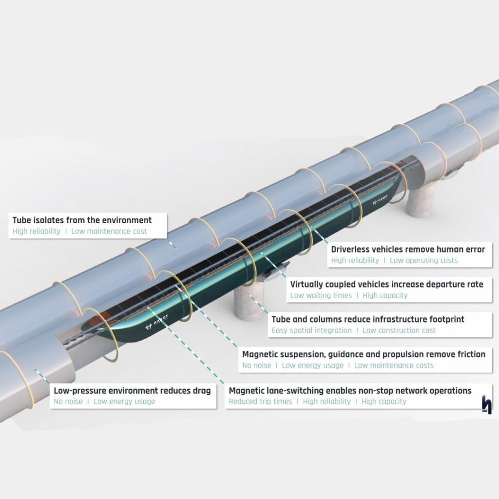
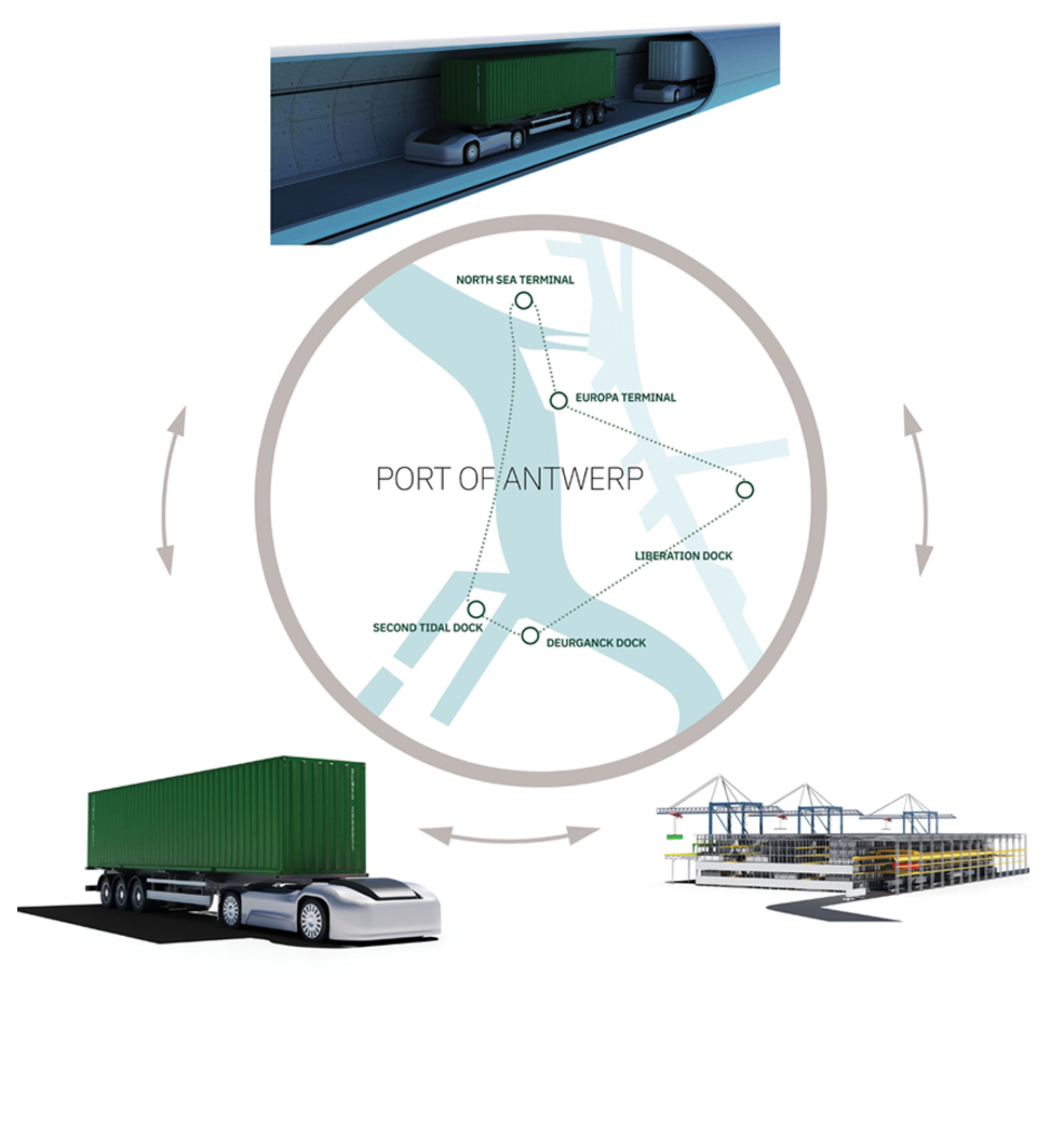
Le Underground Container Mover UCM - Port Loop est un nouveau système de transport multimodal entièrement automatisé qui offre la possibilité de transférer les conteneurs le plus efficacement possible au sein de la zone portuaire/qui permet le transfert le plus efficace possible des conteneurs dans la zone portuaire. Le repositionnement des conteneurs de manière écologique, flexible, fiable et sûre via UCM peut devenir un volant d’inertie pour le transport de conteneurs par route, par rail et par transport maritime. L'UCM – Port Loop offre une solution plus structurelle pour réaliser les ambitions de la Flandre en termes de répartition modale et pour répondre de manière plus adéquate aux attentes européennes en matière d'émissions de gaz à effet de serre.
L’UCM – Port Loop repose sur trois piliers :
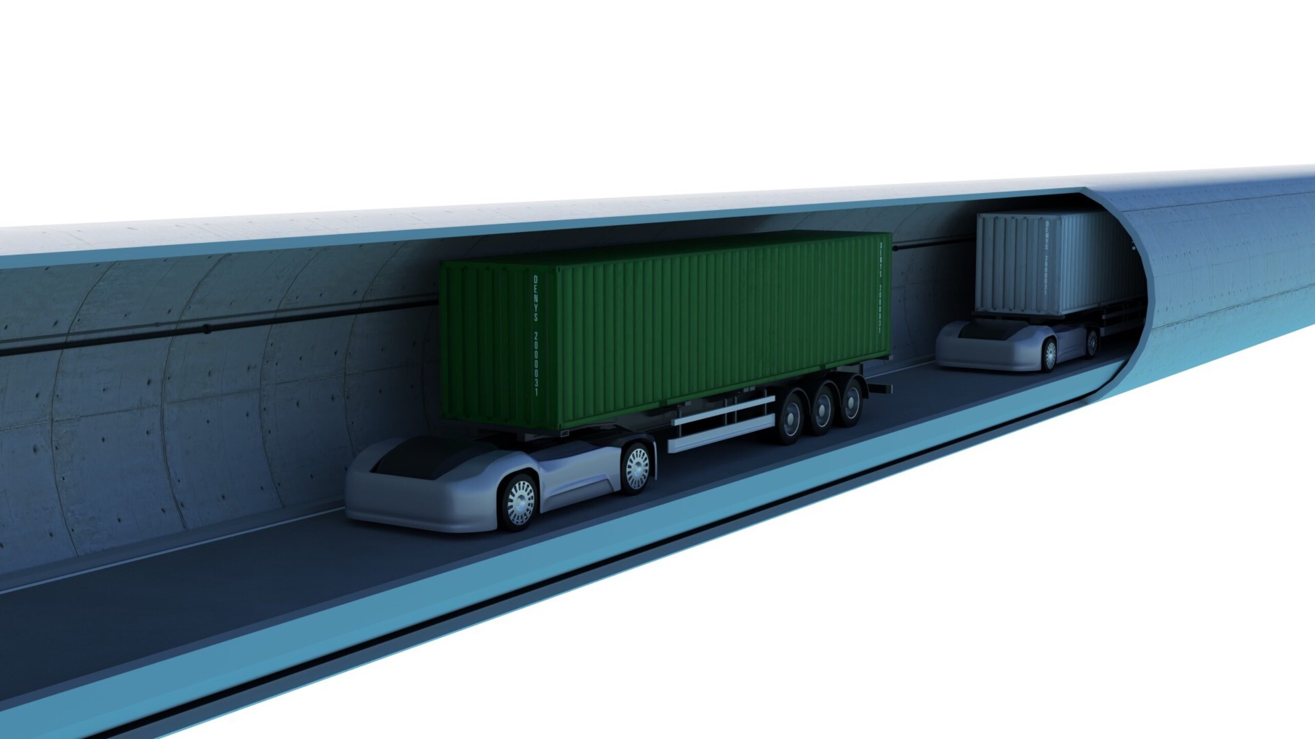
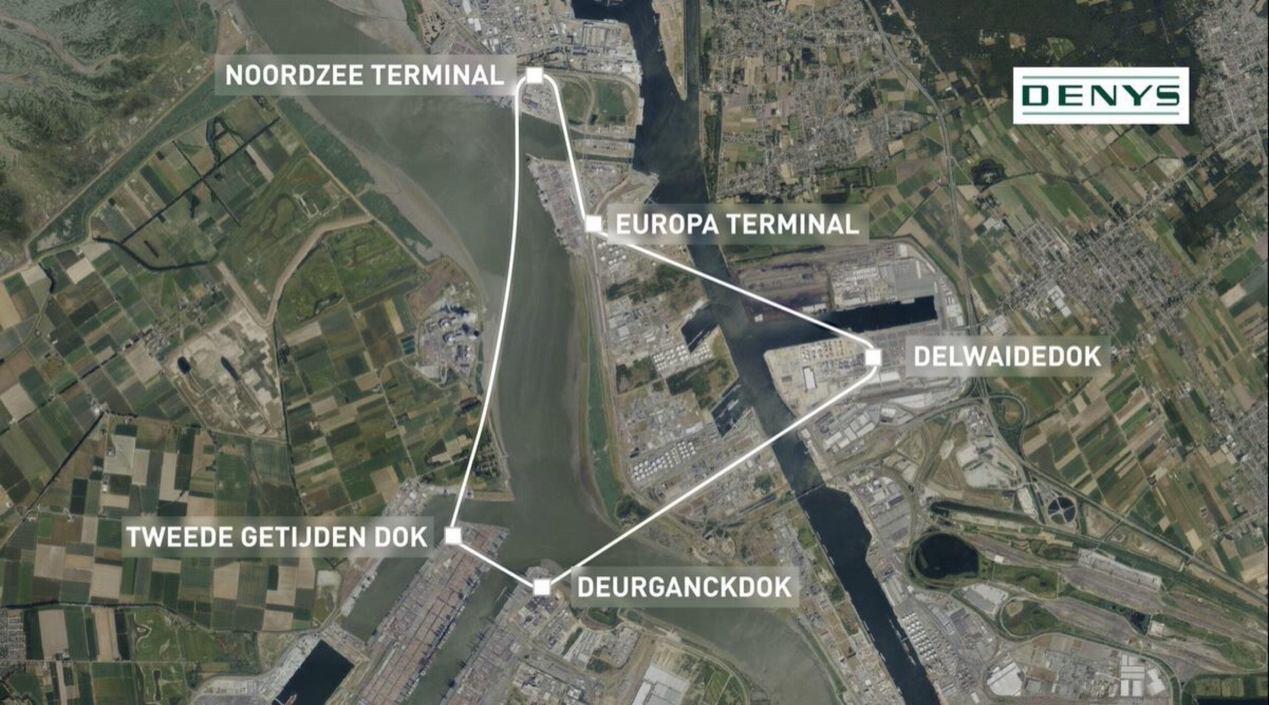
• Un tunnel minimaliste qui relie des emplacements stratégiques en boucle, contournant les obstacles actuels et créant des pôles dans lesquels différents modes de transport peuvent être concentrés et accessibles.
• Des AEV (véhicules électriques autonomes) intelligents et durables, qui peuvent facilement entrer et sortir de la boucle, pour réaliser le débit élevé de conteneurs.
• Si nécessaire, des systèmes automatisés d'empilage de conteneurs pourraient être utilisés, ce qui triplerait la capacité de stockage actuelle par mètre carré et permettrait un accès direct à tous les conteneurs sans avoir besoin de les réorganiser/réarranger.
Pour plus d’informations, jetez un œil à la video.


ANDERE PROJECTEN